- 您现在的位置:买卖IC网 > Sheet目录238 > NUP3112UPMUTAG (ON Semiconductor)TVS QUAD ARRAY LOW CAP 6-UDFN
NUP3112UPMU
ELECTRICAL CHARACTERISTICS
(T A = 25 ° C unless otherwise noted)
Symbol
I PP
V C
V RWM
Parameter
Maximum Reverse Peak Pulse Current
Clamping Voltage @ I PP
Working Peak Reverse Voltage
I F
I
I R V F
I R
V BR
I T
Maximum Reverse Leakage Current @ V RWM
Breakdown Voltage @ I T
Test Current
V C V BR V RWM
I T
V
I F
V F
Forward Current
Forward Voltage @ I F
P pk
C
Peak Power Dissipation
Max. Capacitance @ V R = 0 and f = 1.0 MHz
I PP
Uni ? Directional TVS
ELECTRICAL CHARACTERISTICS (T J = 25 ° C, unless otherwise specified)
Parameter
Reverse Working Voltage (D 1 , D 2 , and D 3 )
Reverse Working Voltage (V 1 )
Breakdown Voltage (D 1 , D 2 , and D 3 )
Breakdown Voltage (V CC )
Reverse Leakage Current (D 1 , D 2 , and D 3 )
Reverse Leakage Current (V CC )
Capacitance (D 1 , D 2 , and D 3 )
Conditions
(Note 1)
(Note 1)
I T = 1 mA, (Note 2)
I T = 5 mA, (Note 2)
@ V RWM
@ V RWM2
V R = 0 V, f = 1 MHz (Line to GND)
Symbol
V RWM1
V RWM2
V BR
V BR2
I R
I R
C J
Min
?
?
5.2
13.5
?
?
?
Typ
?
?
5.5
15
?
?
0.7
Max
4.0
12
?
15.8
1.0
1.0
0.9
Unit
V
V
V
V
m A
m A
pF
1. TVS devices are normally selected according to the working peak reverse voltage (V RWM ), which should be equal or greater than the DC
or continuous peak operating voltage level.
2. V BR is measured at pulse test current I T .
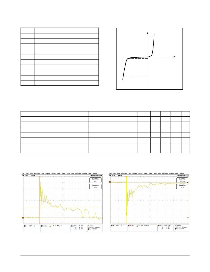
Figure 1. ESD Clamping Voltage Screenshot
Positive 8 kV Contact per IEC61000 ? 4 ? 2
http://onsemi.com
2
Figure 2. ESD Clamping Voltage Screenshot
Negative 8 kV Contact per IEC61000 ? 4 ? 2
发布紧急采购,3分钟左右您将得到回复。
相关PDF资料
NUP3115UPMUTAG
TVS QUAD ARRAY LOW CAP 6-UDFN
NUP4000DR2G
TVS ARRAY BIDIR 400W 15V 8SOIC
NUP4004M5T1G
IC TVS ARRAY QUAD BIDIR 5TSOP
NUP4012PXV6T1G
TVS ARRAY QUAD LOW CAP SOT-563
NUP4060AXV6T1G
IC TVS ARRAY 4LINE SOT-563
NUP4102XV6T1G
IC TVS ARRAY QUAD BIDIR SOT-563
NUP4103FCT1
IC TVS ARRAY QUAD UNI 5FLIPCHIP
NUP4106DR2G
TVS LO CAP 500W 3.3V 8SOIC
相关代理商/技术参数
NUP3115UPMU
制造商:ONSEMI 制造商全称:ON Semiconductor 功能描述:Transient Voltage Suppressors
NUP3115UPMUTAG
功能描述:TVS二极管阵列 LOW CAP TVS ARRAY RoHS:否 制造商:Littelfuse 极性: 通道:4 Channels 击穿电压: 钳位电压:11.5 V 工作电压:2.5 V 峰值浪涌电流:20 A 安装风格:SMD/SMT 端接类型:SMD/SMT 系列: 最小工作温度:- 40 C 最大工作温度:+ 85 C
NUP4000
制造商:ONSEMI 制造商全称:ON Semiconductor 功能描述:Bi-directional TVS Array for High-Speed Data Line Protection
NUP4000DR2G
功能描述:TVS二极管阵列 4 CHAN BIDIRECTIONAL TVS RoHS:否 制造商:Littelfuse 极性: 通道:4 Channels 击穿电压: 钳位电压:11.5 V 工作电压:2.5 V 峰值浪涌电流:20 A 安装风格:SMD/SMT 端接类型:SMD/SMT 系列: 最小工作温度:- 40 C 最大工作温度:+ 85 C
NUP4004M5
制造商:ONSEMI 制造商全称:ON Semiconductor 功能描述:5−Pin Bi−Directional Quad TVS Array
NUP4004M5T1G
功能描述:TVS二极管阵列 5 PIN BIDRECTNL QUAD RoHS:否 制造商:Littelfuse 极性: 通道:4 Channels 击穿电压: 钳位电压:11.5 V 工作电压:2.5 V 峰值浪涌电流:20 A 安装风格:SMD/SMT 端接类型:SMD/SMT 系列: 最小工作温度:- 40 C 最大工作温度:+ 85 C
NUP4012PMUTAG
功能描述:TVS二极管阵列 LOW CAP TVS ARRAY RoHS:否 制造商:Littelfuse 极性: 通道:4 Channels 击穿电压: 钳位电压:11.5 V 工作电压:2.5 V 峰值浪涌电流:20 A 安装风格:SMD/SMT 端接类型:SMD/SMT 系列: 最小工作温度:- 40 C 最大工作温度:+ 85 C
NUP4012PXV6
制造商:ONSEMI 制造商全称:ON Semiconductor 功能描述:Quad Transient Voltage Suppressor Array